Call us: +86-137-2353-4866
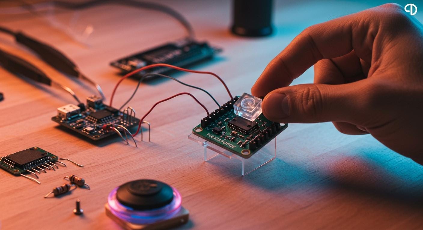
Integration of a flexiforce force sensor begins by connecting the sensor. You need to pick a good resistor. You read the sensor’s output with a microcontroller. SOUSHINE’s force sensing resistor is special in force sensing. It can notice small changes in force very well. The sensor can bend and stretch. This makes it good for wearable technology. It does not cost much and uses little power. This helps many kinds of projects. Anyone can use this technology. Hobbyists, students, and engineers can all use it.
Table of Contents
Key Takeaways
- FlexiForce force sensors measure force by changing resistance when pressed. This makes them great for many projects.
- These sensors are light, cheap, and use little energy. They are good for hobbyists, students, and engineers.
- Picking the right force-sensitive resistor (FSR) depends on what your project needs. Think about how strong, sensitive, and compatible it is.
- FlexiForce sensors can measure many different forces. Some models measure less than 1 pound. Others can measure over 7,000 pounds.
- Good wiring methods, like crimping connectors or using breadboard tabs, help keep the sensor safe during setup.
- A voltage divider circuit with a fixed resistor helps microcontrollers read force changes well.
- Calibration is very important for correct force measurements. Use known weights to make a reference table for your readings.
- FlexiForce sensors are used in many areas, like cars, healthcare, and robots. They help these fields work better.
FlexiForce Force Sensor Basics
What Is a FlexiForce Force Sensor
A flexiforce force sensor tells you how much force is on it. SOUSHINE’s force sensing resistors use new technology for good results. These sensors help people measure force in many projects. The flexiforce force sensor has a special material. This material changes its resistance when pressed. This makes it easy to measure force.
A flexiforce force sensor has many layers. The table below shows the main parts and what they do:
| Material Type | Description |
|---|---|
| Piezoresistive Material | Sits between two flexible polyester sheets |
| Flexible Polyester | Gives support and shape |
| Printed-Silver Conductors | Connects the sensor to other electronics |
| Thickness | About 8 mils, making the sensor light and thin |
How FlexiForce Sensors Work
The flexiforce force sensor changes resistance when you press it. If you do not press it, the resistance is very high. It can be in the megaohm range. When you press it, the resistance goes down. It can go as low as 10 kΩ or less. This change is steady and follows a straight line. The sensor starts with no connection. When you press it, the resistance drops in a straight line. This makes it easy to measure different forces.
- The sensor’s output is steady, so you can trust it.
- Simple circuits can turn the resistance into voltage for a microcontroller.
- The flexiforce force sensor can measure many forces. It can sense less than 1 pound or up to 7,000 pounds. This depends on the model and how you set it up.
Flexiforce force sensors last a long time. Tests show they can handle one million presses with the same load and still work well.
Applications
Flexiforce force sensors are used in many areas. The table below shows some common uses:
| Industry | Application |
|---|---|
| Automotive | Seat detection, brake pressure |
| Healthcare | Patient monitoring, rehab devices |
| Robotics | Touch sensing, grip control |
People use these sensors in cars to check if someone is in a seat. They also measure brake pressure. In healthcare, they help watch patients and help with recovery. Robots use them to feel touch and control grip strength. The flexiforce force sensor gives good results in all these uses.
Force Sensitive Resistor Selection

Choosing the Right FSR
Picking the best force sensitive resistor takes some thinking. Every project is different and needs special things. Some projects need sensors that last a long time. Others need sensors that can notice small changes fast. The table below lists what to look for when picking a force sensitive resistor:
| Criteria | Description |
|---|---|
| Durability | Needed for sensors that face frequent use or tough conditions. |
| Compatibility | Must work with the system’s voltage and current. Sometimes needs special circuits. |
| Price and Value | Budget-friendly options help make projects possible. FSRs often cost less. |
| Length | The area to measure affects the choice of FSR length. |
| Sensitivity | Shows the smallest force the sensor can detect. This matters for many projects. |
| Response | Tells how fast the sensor reacts to force. This is key for advanced uses. |
If a student builds a robot hand, they need a sensor that is very sensitive and reacts fast. If an engineer makes a car seat sensor, they care more about how strong and compatible it is. Every project should match what it needs with what the sensor can do.
SOUSHINE Product Options
SOUSHINE has different force sensitive resistors for many uses. Each kind works best for certain jobs. The table below shows two main types:
| Feature | Shunt Mode FSR | Thru Mode FSR |
|---|---|---|
| Force Range | Wide (light to heavy) | Narrow (light to moderate) |
| Sensitivity | Good for many force levels | High for small force changes |
| Sensing Response | Less linear | More linear |
| Typical Applications | Automotive, medical, electronics | Robotics, automation, touch |
| Cost | Lower | Slightly higher |
| Integration | Simple | Simple |
Shunt Mode FSRs are good for cars and medical tools. Thru Mode FSRs are better for robots and machines. Both types are easy to use in circuits. SOUSHINE gives people many choices so they can pick the right sensor for their project.
Tools and Accessories
To build a project with a force sensitive resistor, you need the right tools. The table below lists some helpful things:
| Tool/Accessory | Description |
|---|---|
| FlexiForce Sensor Characterization Kit | Helps engineers test sensor performance in a controlled setting. |
| FlexiForce Prototyping Kit | Supports design and testing during early project stages. |
| FlexiForce Quickstart Board | Makes setup and testing of sensors easy. |
| Load Concentrators | Spread force over the sensor for better readings. |
| FlexiForce Integration Knowledge Base | Offers documents and guides for every step of sensor use. |
You also need a microcontroller, some resistors, and simple wiring tools. These things help you test and use the force sensitive resistor. Good tools and accessories help you get better results and save time.
Tip: Try using a prototyping kit first. It helps you learn how the force sensitive resistor works before you build your final project.
Force Sensitive Resistor Hookup Guide
Sensor Pinout
FlexiForce force sensors have different pinout types. Each type is made for a special use. The table below lists the main connection types and what they do:
| Connection Type | Description |
|---|---|
| Open Tail A | Good for custom ends. Users can make their own connectors. |
| Open Tail B | Works for direct board connections with special glue. |
| ZIF Without Overcoat | Fits designs that need a thin connector. |
| ZIF With Overcoat | Adds strength for sensors used many times. |
| Crimped Contacts | Lets users solder wires or use connectors. |
| Crimped Housings | Connects to wire leads or board headers. |
Each pinout type helps connect the sensor to a circuit. ZIF connectors are good for small spaces. Crimped contacts are helpful if you need to solder or use normal connectors.
Wiring Methods
There are a few ways to connect a FlexiForce sensor to a circuit. Each way has its own good points:
- Soldering: Advanced users often pick this way. They must use low heat and work fast. Too much heat can hurt the sensor.
- Crimping Connectors: Amphenol FCI Clincher connectors make a strong link. This way does not use heat, so it keeps the sensor safe.
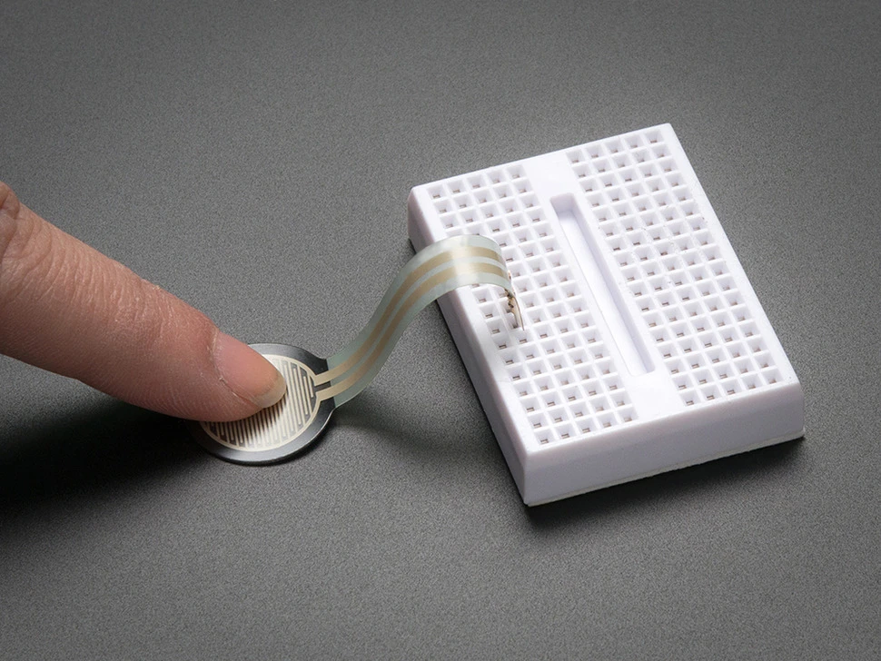
- Breadboard-Compatible Tabs: These tabs fit into breadboards or jumper wires. This way is good for testing and quick setups.
Soldering the tabs of a FlexiForce sensor needs care. The soft material can melt if the iron is too hot or stays too long. Crimping connectors stop this problem. Breadboard tabs help with fast changes when testing.
Tip: Beginners should use breadboard tabs or crimping connectors. These ways lower the chance of breaking the sensor.
Breadboard and PCB Setup
How you set up a FlexiForce sensor on a breadboard or PCB depends on your project. The table below shows common ways to connect and what they are for:
| Method of Connection | Description |
|---|---|
| Breadboard Compatible Tabs | Tabs fit into breadboards or jumper wires for easy testing. |
| 2.54mm Pitch Screw Terminal | Connects sensors on breadboards, but may not always fit tight. |
| IC Hooks | Good for short tests. Not safe for long use. |
| Alligator Clips | Can grip tabs but might hurt the sensor’s surface. |
| Soldering | Best for finished builds. Use low heat to keep the sensor safe. |
On a breadboard, you can put the sensor tabs right in. You can also use jumper wires for quick changes. On a PCB, people often use crimped housings or solder the sensor. Soldering gives a strong link for finished projects. Keep the iron cool and work fast to protect the sensor.
Note: Always check the sensor’s datasheet for the best way to connect. This helps you avoid mistakes and keeps the sensor working well.
A force sensitive resistor hookup guide helps you pick the right way to connect. It also shows how to keep the sensor safe and get good results.
FlexiForce Pressure Sensor Circuit
Circuit Diagram
A flexiforce pressure sensor works best with a simple analog circuit. Many engineers use a voltage divider or an op-amp circuit. These circuits help read changes in force. The voltage divider is popular because it is easy to make. It is also simple to understand.
The schematic diagram shows an analog circuit for a flexiforce pressure sensor. It uses an inverting op-amp setup. This setup has important parts for signal conditioning. The op-amp makes the sensor’s output bigger. This helps a microcontroller read the signal.
The voltage divider circuit uses the flexiforce pressure sensor as one resistor. A fixed resistor is the other part. When you press the sensor, its resistance changes. This change makes a different voltage. The microcontroller can read this voltage.
- Flexiforce pressure sensors act like resistors in a circuit. People can pick different circuit types for their needs.
- The sensor’s resistance goes down when you press harder. A resistance vs force curve shows how the voltage divider gives a changing voltage.
- The voltage divider’s straightness can change. This lets people get different sensitivities for different force levels.
A basic circuit diagram for a flexiforce pressure sensor has these steps:
- The sensor is in series with a fixed resistor.
- One end of the sensor goes to the voltage supply.
- The other end of the sensor goes to the fixed resistor.
- The fixed resistor connects to ground.
- The voltage between the sensor and resistor goes to the microcontroller’s analog input.
This setup lets people measure force by reading voltage changes.
Resistor Selection
Picking the right resistor for a flexiforce pressure sensor circuit is important. The resistor changes how sensitive the circuit is. It also affects how well it measures force.
Calculating Value
People must think about a few things when picking a resistor value:
- The resistance of the flexiforce pressure sensor.
- The current they want through the sensor.
- The type of circuit, like half-bridge or Wheatstone bridge.
To find the resistor value, people look at the sensor’s resistance range. For example, if the sensor’s resistance drops from 1 MΩ to 10 kΩ, the fixed resistor should be close to the lowest resistance. This gives the best sensitivity. If the sensor will measure small forces, a higher resistor value helps. For bigger forces, a lower resistor value is better.
A simple formula helps:
Vout = Vin * (Rfixed / (Rfixed + Rsensor))
People set Vin as the supply voltage. Rfixed is the resistor they pick. Rsensor is the flexiforce pressure sensor’s resistance. By changing Rfixed, people change the output voltage range.
Sensitivity Impact
The resistor value changes how sensitive the circuit is. A higher resistor value makes the circuit more sensitive to small forces. A lower resistor value helps measure bigger forces. People must match the resistor to the force range they want to measure.
- High resistor values make the circuit more sensitive to light touches.
- Low resistor values help measure strong forces.
- The resistor also changes the voltage sent to the microcontroller.
People try different resistor values to find the best setup for their project.
Power Supply
The power supply changes how well the flexiforce pressure sensor works. People should use a steady voltage source for the best results.
- An op-amp circuit makes the flexiforce pressure sensor work better.
- For higher force measurements, people use a lower drive voltage, like -0.5 V or -0.25 V, and a feedback resistor of at least 1 kΩ.
- For lower force measurements, people use a higher drive voltage and a bigger feedback resistor.
Standard multimeters can measure the sensor, but they do not give a steady voltage. A steady voltage supply helps the sensor give steady readings. Special tools make calibration easier than regular multimeters.
A table shows good power supply choices:
| Measurement Type | Drive Voltage | Feedback Resistor Value | Notes |
|---|---|---|---|
| High Force | -0.5 V | ≥ 1 kΩ | Lower voltage, lower resistor |
| Low Force | +5 V | ≥ 100 kΩ | Higher voltage, higher resistor |
| General Use | +3.3 V | 10 kΩ – 100 kΩ | Good for most projects |
People pick the power supply and resistor based on the force range they want to measure. This helps the flexiforce pressure sensor work well in many projects.
Tip: Always test your circuit with your chosen power supply and resistor before you finish your design. This makes sure the flexiforce pressure sensor gives good and steady readings.
Microcontroller Integration
Arduino Connection
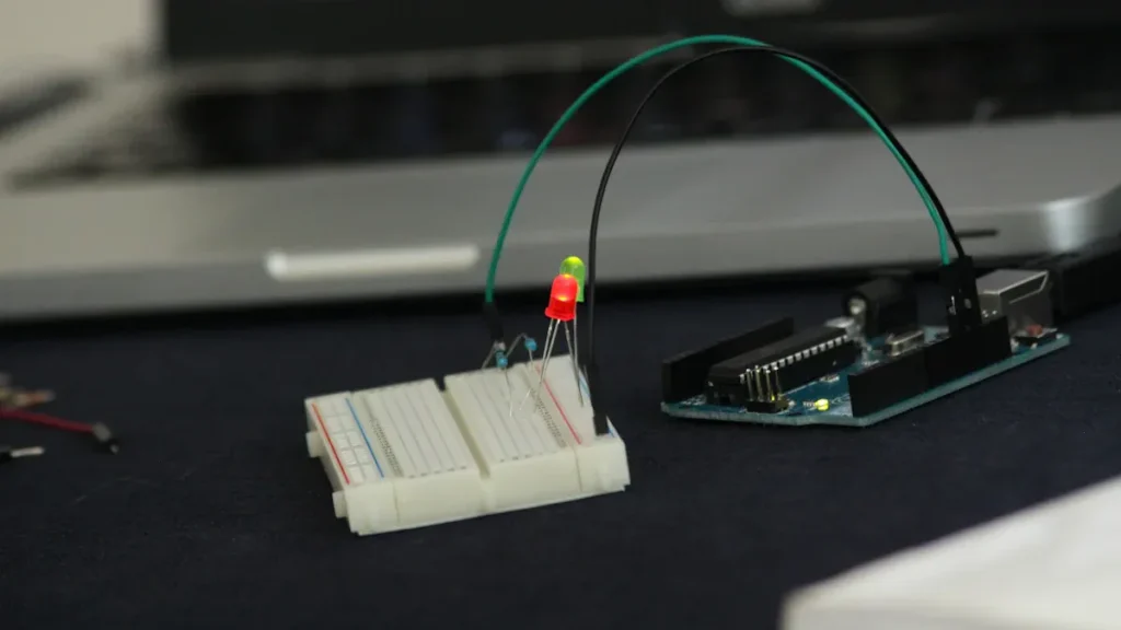
Lots of electronics projects use arduino boards with FlexiForce force sensors. The arduino reads the sensor’s data using a simple setup. You connect the sensor to an analog input pin on the arduino. Most people use analog pin A0 for this. The other side of the sensor connects to a resistor, and then to ground. This makes a voltage divider. As you press the sensor, the voltage changes. The arduino can read this changing voltage.
To hook up the sensor, do these steps:
- Attach one end of the FlexiForce sensor to the arduino’s 5V pin.
- Connect the other end of the sensor to analog pin A0.
- Put a resistor between analog pin A0 and ground.
- The arduino checks the voltage at A0. This voltage changes when you press the sensor.
This setup lets the arduino measure force with its analog-to-digital converter. Using the sensor with the arduino helps you collect and use force data easily.
Sample Code
The arduino gets the sensor’s voltage and turns it into a number. The code below shows how to read the FlexiForce sensor with an arduino. It prints the value to the serial monitor.
float cf = 19.5; // calibration factor
int ffs1 = A0; // FlexiForce sensor is connected to analog pin A0 of Arduino or Mega.
int ffsdata = 0;
float vout;
void setup()
{
Serial.begin(9600);
pinMode(ffs1, INPUT);
}
void loop()
{
ffsdata = analogRead(ffs1);
vout = (ffsdata * 5.0) / 1023.0;
vout = vout * cf;
Serial.print("Flexi Force sensor: ");
Serial.print(vout,3);
Serial.println("");
delay(100);
}
This code uses analogRead to get a number from the sensor. It figures out the output voltage and uses a calibration factor. The arduino sends the result to the serial monitor every 100 milliseconds.
Data Interpretation
The arduino gives a number from 0 to 1023 for each reading. You need to know what these numbers mean to measure force. The FlexiForce sensor can do both absolute and relative measurements.
- Absolute measurement matches the voltage to a force unit, like newton or kilogram.
- Relative measurement looks at how the voltage changes as force changes. This is good if the sensor drifts over time.
- For relative use, you watch the voltage difference as you press the sensor. This way, you get steady results even if the sensor changes a bit.
To get real force values, you should calibrate the sensor. Put known weights on the sensor and write down the arduino readings. This helps you make a table or formula that links readings to real force. The arduino can then show force in the units you want.
Troubleshooting and Tips
Common Issues
FlexiForce force sensors are used in many areas. Sometimes, problems can stop projects or cause safety issues. The table below lists some problems and what can happen:
| Industry | Consequence | Example |
|---|---|---|
| Robotics | Work stops | Robot arm drops parts |
| Automotive | Safety danger | Airbag does not open |
| Medical | Patient injury | Surgical tool gives wrong force |
| Aerospace | Machine breaks | Missed wing stress warning |
Engineers check the sensor’s range and detail before starting. They use ISO and ANSI rules to set up force calibration. They fix mistakes and things outside that change readings. Software setup matters a lot. Engineers put in drivers and set up programs to read sensor data. Sometimes, they need special code or plugins for the sensor to work.
Tip: If you do not get readings, check all wires first. Make sure your software matches the sensor type.
Noise Reduction
Electric noise can mess up sensor readings. Good design helps keep noise low. These steps help keep signals clean:
- Ground all tools and equipment.
- Keep sensor wires away from strong AC power wires.
- Use shielded cables for sensor wires.
- Put high AC power wires in their own tubes.
- Use surge protectors for circuits.
- Do not tie high and low power wires together.
- Cross high and low power wires at right angles if needed.
- Keep panels and wires away from big motors.
Doing these steps helps the sensor give steady readings. Guides or tutorials show how to set up circuits to stop noise.
Accuracy Improvement
Getting correct force readings helps projects work well. These actions make accuracy and repeat tests better:
- Use a good holder to press force the same way each time.
- Keep the test area’s temperature and humidity steady.
- Calibrate the sensor often.
- Use the same steps to take off force for each test.
- Watch for sensor drift and timing problems.
- Pick the right surface and contact materials.
Guides or tutorials show how to set up tests and calibrate sensors. Checking often helps keep the sensor working well. Many engineers use guides to learn the best ways to measure force. Tutorials help new users avoid mistakes and get better results.
Note: Always follow the steps in your guide or tutorial. This helps you get the best results and avoid common problems.
Resources and Next Steps
SOUSHINE and Other Suppliers
Many companies sell FlexiForce force sensors for electronics projects. SOUSHINE is known for good quality and helpful support. Other trusted companies also have many sensor choices. Here are some well-known suppliers:
- SOUSHINE
- Interlink
- Tekscan
- SparkFun
- Adafruit
- Flexiforce
- Sensitronics
Each company has different sensor types and extra parts. SOUSHINE’s website has a product page with details and tips for using the sensors. Tekscan gives a guide to help new users get started. These resources help people pick the right sensor and begin their project with confidence.
Further Reading
Learning more about FlexiForce force sensors helps people make better projects. Many websites give step-by-step guides and tips. The table below lists some helpful kits and guides:
| Resource | Description |
|---|---|
| FlexiForce OEM Design & Integration Knowledge Base | A library with guides, how-to videos, and tips for using sensors. |
| FlexiForce Sensor Characterization Kit | Has software, quickstart guides, and manuals for testing sensors. |
| FlexiForce Prototyping Kit | Gives software, quickstart guides, and manuals for building with FlexiForce sensors. |
People can find a tutorial for almost every part of the process. Good guides show how to use load concentrators and put sensors in place. Electrical guides explain how to pick circuits, change sensitivity, and calibrate. Each tutorial gives clear steps for setup and testing. Reading a guide before starting helps you avoid mistakes.
Tip: Look at a guide or tutorial before you build your circuit. This helps you learn each step and get better results.
Project Ideas
FlexiForce force sensors can be used in many fun projects. The list below shows some popular ideas:
- Finger Controlled Wheelchair: This project lets you move a wheelchair with finger pressure.
- Wrist Controlled Robotic Arm: The arm moves when you press with your wrist.
- Sign Language Translator: The device turns hand signs into spoken words.
- Gesture Based Robotic Arm: Hand movements control the robotic arm.
- Animatronic Hand using Glove: A glove lets you control a robotic hand for demos.
Each project uses a guide or tutorial for setup and coding. Students and engineers can follow a tutorial to learn new things. A guide shows how to connect the sensor and read its data. Trying a new project helps people see how FlexiForce sensors work in real life.
To use a FlexiForce force sensor, follow these easy steps: First, put together your hardware. Next, connect the sensor with solder tabs or jumper wires. Then, make a voltage divider circuit. Pick a resistor that fits the sensor’s range. Last, test everything to make sure it works right.
SOUSHINE FSRs are used in lots of projects. Some cool uses are smart insoles and robotic hands:
| Application Area | Description |
|---|---|
| Smart Insole Devices | Check foot pressure to study how people walk. |
| Robotic Hands | Measure fingertip pressure for better touch. |
SOUSHINE gives help with tech support, custom designs, and direct contact. People can try new ideas and get help at every step of their project.
FAQ
What is a force-sensitive resistor?
A force-sensitive resistor changes resistance when you press it. The sensor can tell how much force you use. It does this by checking how much the resistance goes down. Many projects use these sensors to sense touch or pressure. They help measure force in robotics, healthcare, and electronics.
How does a force-sensitive resistor measure force?
A force-sensitive resistor measures force by changing resistance. When you press the sensor, the resistance drops. The circuit sees this change and turns it into voltage. The microcontroller reads the voltage to find out the force.
Can a force-sensitive resistor detect small and large forces?
A force-sensitive resistor can sense both light and strong presses. The sensor works for small touches and big pushes. The force range depends on the sensor type and the resistor in the circuit. You can change the circuit to measure different force levels.
How do you connect a force-sensitive resistor to an Arduino?
Connect one end of the force-sensitive resistor to the Arduino’s 5V pin. Connect the other end to an analog input pin. Put a resistor between the analog pin and ground. This makes a voltage divider. The Arduino reads the voltage to measure force.
What is an example Arduino sketch for reading a force-sensitive resistor?
The example arduino sketch reads the analog value from the force-sensitive resistor. It changes the value to voltage and prints it to the serial monitor. This sketch lets you see how force changes the sensor’s output.
How do you calibrate a force-sensitive resistor?
To calibrate a force-sensitive resistor, put known weights on the sensor. Write down the readings for each weight. Make a table that matches force to sensor output. Use this table to change future readings into force values. Calibration makes the sensor more accurate.
Why does the force reading sometimes change without touching the sensor?
Force readings can change because of temperature, humidity, or electrical noise. These things affect the sensor’s output. Shielding wires and keeping the area steady helps stop unwanted changes. Calibrating often also helps keep readings steady.
Can force-sensitive resistors be used in wearable devices?
Force-sensitive resistors work well in wearable devices. They measure force from body movements, steps, or grip. Their thin and bendy design fits many wearable uses. Engineers use them in smart insoles, gloves, and health monitors.