Call us: +86-137-2353-4866
Calibrating and testing a force sensing resistor with Arduino is simple. Many beginners think this process is easy to do, especially with SOUSHINE products. The setup needs only a few parts and gives fast results. Good calibration helps make force sensing work well in projects. The table below explains why fsr with arduino is great for people new to sensors.
| Feature | Force Sensing Resistor (FSR) | Other Sensor Types |
|---|---|---|
| Calibration Complexity | Easy to do | Harder to set up |
| Availability of Tutorials | Lots to find | Not as many |
| Required Components | Only a few needed | Usually needs more |
| Beginner-Friendliness | Very easy for beginners | Can be harder |
Table of Contents
Key Takeaways
- Calibrating an FSR with Arduino is easy. You only need a few parts. This makes it good for beginners.
- Calibration helps you get correct readings. It matches the sensor’s output to real forces. This stops mistakes in your projects.
- Use a voltage divider circuit with a 10kΩ resistor. This helps the Arduino read changes in the FSR’s resistance.
- Always calibrate the FSR in the same place you will use it. This gives you the best results.
- Take many readings for each weight during calibration. This helps remove random changes and makes it more accurate.
- Check all wires and make sure the FSR is flat and steady. This stops the readings from jumping around.
- Write down your calibration data. This helps you see changes and keeps the sensor accurate over time.
- Test and recalibrate the FSR often. This keeps your measurements correct in different uses.
What is a Force Sensing Resistor?
FSR Basics
SOUSHINE makes force sensing resistors for many jobs. These sensors can measure force and pressure. They have a bendable base, a spacer, and a layer that conducts electricity. The bendable base lets the sensor fit into different spaces. The layer that conducts electricity changes its resistance when pressed. SOUSHINE has many shapes and sizes, so people can pick the best one for their project.
| Component/Feature | SOUSHINE FSRs | Other Brands |
|---|---|---|
| Flexible Substrate | Yes | Varies |
| Conductive Materials | Yes | Varies |
| Operational Principle | Decrease in resistance with pressure | Similar piezoresistive behavior |
| Shape and Size Variety | Many shapes and sizes available | Limited options |
How FSRs Work
A force sensing resistor changes its resistance when you press it. The special material inside reacts to pressure. When you push harder, the tiny parts inside touch the electrodes more. This makes the resistance go down. The sensor uses percolation and quantum tunneling to change how electricity moves. Both the contact resistance and the area for current change when you press it. This steady change lets people measure force well.
Tip: The sensor does not just turn on or off. It gives many values, so you can tell how much force is there.
Applications
Many businesses use force sensing resistors. In sports clothes, they check foot pressure in shoe insoles. Medical tools use them to sense force for giving medicine and checking bed pressure. Robots use these sensors to know how much pressure their arms use. Inventory systems use them to watch the weight on shelves. User controls use these sensors as buttons that can do different things.
| Industry | Application Description |
|---|---|
| Athletic Apparel | Detects foot pressure in shoe insoles. |
| Medical Applications | Senses force for medication management and bed pressure checks. |
| Robotics | Provides feedback on pressure used by robotic arms. |
| Inventory Control | Monitors weight on shelves for inventory management. |
| User Interface Controls | Functions as adjustable buttons for various actions. |
A force sensing resistor works well in many areas. SOUSHINE makes sensors that fit what these businesses need.
Why Calibrate an FSR?
Calibration Purpose
Calibration helps people get correct readings from a force sensing resistor (FSR). Each FSR can show different numbers, even if they are from the same brand. Small changes in how the sensor is made or used can change its output. When people calibrate an FSR, they match the sensor’s numbers to real forces. This step makes sure the sensor gives numbers that make sense in a project.
Many things can change how an FSR works. Temperature, the shape of the surface, and how soft or hard the material under the sensor is can all change the readings. For example, if someone uses an FSR on a curved surface like an arm, the sensor may act differently than on a flat table. If the temperature goes up or down, the sensor’s response can change. Each sensor needs calibration in the place and way it will be used. This helps stop mistakes and keeps the readings correct.
Note: Calibrating in the real place, not just in the lab, helps the sensor work better in the final project.
Measurement Accuracy
Getting correct measurements is important in every project. Calibration makes measurements better by removing errors and making the sensor’s output match real forces. Without calibration, the numbers from the FSR may not show the real pressure or weight. This can cause problems, especially in projects where safety or health matters.
To get good results, people should follow these steps:
- Write down the sensor’s value when nothing presses on it. This gives a starting point, called the baseline.
- Put known weights on the sensor and record the readings. Do this with several weights to make a chart or curve.
- Use software tools, like a moving average, to smooth out jumps or noise in the data.
A table can help show why calibration is important:
| Step | What It Does | Why It Matters |
|---|---|---|
| Baseline Reading | Finds the sensor’s zero point | Removes background noise |
| Known Weights | Matches readings to real forces | Builds a calibration curve |
| Data Smoothing | Reduces random changes in output | Gives steady, clear results |
Mechanical conditions, like how much the sensor bends or how soft the surface is, can change the sensor’s response. Calibrating in the same place as the final project helps people get the best results. Each FSR may need its own calibration because no two sensors act exactly the same. This careful process helps people trust the numbers they see from their SOUSHINE FSR.
Materials for FSR with Arduino
You need just a few parts to set up an fsr with arduino. Each part is important for making the sensor work well. The lists and tables below show what you need for your project.
Required Parts
SOUSHINE FSR
SOUSHINE makes force sensing resistors for many projects. These sensors give good readings for different forces. You can pick shapes and sizes that fit your project. The company helps customers and has fair prices. Many people choose SOUSHINE because it is flexible and works well.
- Good readings for different forces
- Many shapes and sizes to choose from
- Helpful customer support
- Fair prices for good quality
Arduino Board
An Arduino board reads signals from the fsr with arduino. The Arduino Uno is a favorite for many people. It connects to a computer and works with lots of sensors.
10kΩ Resistor
A 10kΩ resistor is part of the voltage divider circuit. This resistor helps the Arduino see changes in resistance from the fsr with arduino. Some kits have different resistors, but 10kΩ is used most often.
Breadboard & Wires
A mini breadboard holds all the parts together. Jumper wires connect the fsr with arduino, the Arduino board, and the resistor. These parts make building and changing the circuit easy.
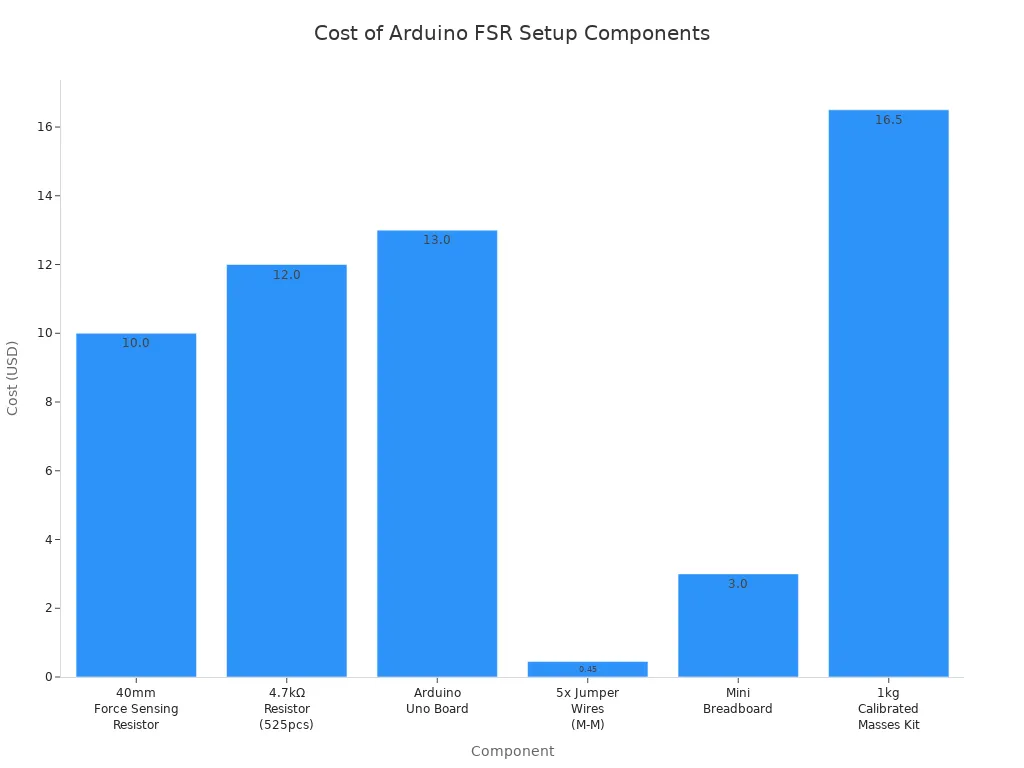
The table below shows how much each part costs:
| Component | Cost |
|---|---|
| 40mm Force Sensing Resistor | $10.00 |
| 4.7kΩ Resistor (525pcs) | $12.00 |
| Arduino Uno Board | $13.00 |
| 5x Jumper Wires (Male-to-Male) | $0.45 |
| Mini Breadboard | $3.00 |
| 1kg Calibrated Masses Kit (8pcs) | $16.50 |
Optional Tools
Some people use extra tools to make their fsr with arduino projects better. A multimeter checks the sensor and the circuit’s resistance. Calibrated weights help test if the sensor is accurate. These tools help you get good results and find problems early.
Tip: A multimeter can show if the fsr with arduino circuit works before you upload code.
You only need a few parts for a full fsr with arduino setup. Each part helps the sensor work and gives clear data. With these materials, you can start building and testing your own force sensing projects.
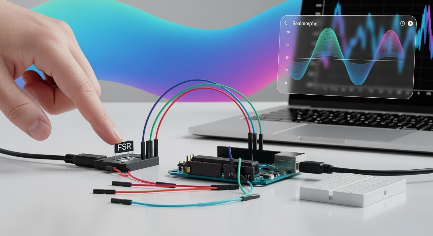
Setup: FSR with Arduino
Circuit Diagram
A simple circuit diagram helps you connect the SOUSHINE Force Sensing Resistor (FSR) to an Arduino board. The setup uses a voltage divider. This lets the Arduino see changes in resistance when you press the FSR. The table below shows how each part connects in the circuit:
| Component | Connection Description |
|---|---|
| Force Sensing Resistor (FSR) | Connect one terminal to the analog input of Arduino. |
| 4.7kΩ Resistor | Connect in series with the FSR to form a voltage divider. |
| Arduino | Measure the voltage drop across the 4.7kΩ resistor. |
This setup lets the Arduino read different voltages when you press the FSR. The voltage divider is important. It changes the FSR resistance into a voltage the Arduino can measure.
Tip: Pick a resistor value that matches the force you expect. Lower values work better for strong forces. Higher values are good for lighter forces.
Wiring Steps
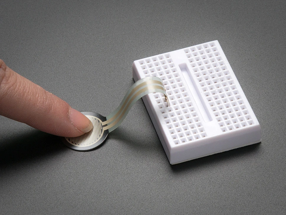
FSR Placement
Putting the FSR in the right spot on the breadboard helps you get good readings. Place the FSR so both legs fit tightly in the breadboard slots. This keeps the sensor steady and stops mistakes during measurement. The FSR should be flat, with no bends or twists. This helps make sure resistance only changes from pressing on it.
| Factor | Impact on Accuracy and Reliability |
|---|---|
| Calibration Conditions | Measurement differences can occur if calibration and use conditions differ. |
| Surface Curvature | Curved surfaces can cause errors unless accounted for. |
| Shear Stress | Shear stress may reduce FSR readings. |
| Static vs. Cyclic Load | Different loading types affect readings. |
| Sensor Variability | Calibrate each FSR individually for best results. |
Voltage Divider
The voltage divider is a main part of the circuit. It uses the FSR and a resistor together. One end of the FSR goes to the Arduino’s voltage pin (5V). The other end connects to one leg of the resistor. The free leg of the resistor goes to the ground (GND) pin. The spot where the FSR and resistor meet connects to an analog input pin on the Arduino.
- The voltage divider makes a changing voltage for the Arduino.
- This setup lets the Arduino see resistance changes in the FSR when you press it.
- The output voltage gets higher as you press harder, showing a link between force and voltage.
With a 5V supply and a 10kΩ pull-down resistor, the FSR has high resistance when no pressure is there. When you press harder, the resistance drops. The voltage at the analog pin goes up. This change lets the Arduino measure force well.
Connection Check
Before you run any code, check all connections. Loose wires or bad contact can cause mistakes or jumpy readings. Try these tips:
- Use jumper wires or heat shrink tubing to keep connections tight.
- Do not solder the FSR directly to protect it.
- Make sure all wires fit snug in the breadboard.
- Keep pressure even on the FSR during calibration for better results.
Note: A multimeter can help you check the circuit before you upload code. Good connections and even pressure help the FSR give steady data.
If you follow these steps, you can set up the SOUSHINE FSR with Arduino for good and repeatable measurements. Putting the sensor right, using a working voltage divider, and making sure connections are secure all help you get good results.
Arduino Code
Sample Code
Below is a sample Arduino code for reading values from a SOUSHINE Force Sensing Resistor. This code helps collect resistance data and sends it to the serial monitor.
// RP-S40-SR Force Sensing Resistor
// Printing out resistance values from the voltage divider

int FSR_pin = A0; // select the input pin for the potentiometer
int avg_size = 10; // number of analog readings to average
float R_0 = 4700.0; // known resistor value in [Ohms]
float Vcc = 5.0; // supply voltage

void setup() {
  Serial.begin(9600);
}

void loop() {
  float sum_val = 0.0; // variable for storing sum used for averaging
  float R_FSR;
  for (int ii=0; ii<avg_size; ii++){
    sum_val += (analogRead(FSR_pin)/1023.0)*5.0; // sum the 10-bit ADC ratio
    delay(10);
  }
  sum_val /= avg_size; // take average

  R_FSR = (R_0/1000.0)*((Vcc/sum_val)-1.0); // calculate actual FSR resistance

  Serial.println(R_FSR); // print to serial port
  delay(10);
}
This code reads the analog value from the FSR, averages several readings, and calculates the resistance. The serial monitor displays the resistance value.
Code Explanation
The code starts by setting the FSR pin and the resistor value. The setup function begins serial communication. The loop function collects analog readings from the FSR pin. It takes ten readings and averages them. This step helps reduce noise and gives a steady value.
The code then calculates the FSR resistance using the voltage divider formula. The formula uses the known resistor value and the measured voltage. The code prints the resistance to the serial monitor. When someone presses the FSR, the resistance drops. The serial monitor shows this change in real time.
This structure helps users see how much force they apply. The code uses simple math and clear steps. Each part of the code has a purpose. The averaging step makes the readings more reliable. The serial output helps users check the sensor’s response.
Upload Steps
Follow these steps to upload the code and start testing the SOUSHINE FSR:
- Gather all components: Arduino Uno, SOUSHINE FSR, 10kΩ resistor, breadboard, and jumper wires.
- Connect the FSR to the 5V pin and A0 on the Arduino. Connect the 10kΩ resistor from A0 to ground.
- Open the Arduino IDE. Copy and paste the sample code into a new sketch.
- Connect the Arduino board to the computer using a USB cable.
- Select the correct board and port in the Arduino IDE.
- Click the upload button to send the code to the Arduino.
- Open the serial monitor in the Arduino IDE to view the resistance values.
- Press the FSR and watch the numbers change as you apply force.
Tip: If the serial monitor does not show values, check the wiring and make sure the correct port is selected.
These steps help users set up, upload, and test the SOUSHINE FSR with Arduino. The process gives clear feedback and helps users understand how the sensor works.
Force Sensing Resistor Calibration
Calibration Steps
When you calibrate a SOUSHINE force sensing resistor with Arduino, you get better force readings. You use a 10kΩ pull-down resistor in a voltage divider circuit. This setup lets the Arduino see voltage changes when you press on the sensor.
Baseline Reading
- Put the force sensitive resistor flat on a table.
- Hook up the sensor to the Arduino with the voltage divider.
- Check the sensor reading when nothing is pressing it. This number is your starting or zero-force value.
- Save this number so you can compare it later.
Tip: Make sure the sensor stays flat and does not slide while you calibrate.
Known Weights
- Put a weight you know, like a 10g mass, on the sensor.
- Wait a few seconds so the number on the Arduino stops changing.
- Write down the number you see from the Arduino.
- Do these steps again with other weights, like 20g, 50g, and 100g.
- If you need to, use a 3D printed piece to spread the weight out.
| Weight (g) | Sensor Output (ADC Value) |
|---|---|
| 0 | [Baseline Value] |
| 10 | [Value 1] |
| 20 | [Value 2] |
| 50 | [Value 3] |
| 100 | [Value 4] |
This table shows how the sensor’s number changes with different weights.
Data Recording
- For each weight, take more than one reading.
- Write down all the numbers and find the average for each weight.
- Make a graph with the average sensor number and the weights.
- Draw a curve on the graph, like a log-log line, to make a calibration curve.
Note: Taking many readings helps stop mistakes from things like temperature or the shape of the surface. This step makes your calibration more correct.
Code Adjustment
You can make your calibration better by changing the Arduino code a little:
- Press on the sensor in the same way each time you calibrate.
- Use weights that are measured to make a clear link between resistance and force.
- Draw a log-log curve with the resistance data for better results.
You can add lines in the Arduino code to average more numbers or save data for later. You can also change the code to match the weights you use in your calibration.
Callout: Doing the same calibration steps and writing down your data carefully helps you get good results from your SOUSHINE sensors.
Testing and Results
Running Tests
Testing a calibrated SOUSHINE Force Sensing Resistor with Arduino is easy. You need to follow a few simple steps. Each step checks if the sensor works right and if the calibration is still good.
- Wiring Configuration: Connect the FSR to the Arduino using a voltage divider. This lets the Arduino see changes in resistance when you press on the sensor.
- Arduino Code: Upload code that reads and shows resistance values from the FSR. Make sure the code matches how you set up the calibration.
- Calibration Procedure: Put known weights on a flat piece, like a 3D printed part, over the FSR. Write down the resistance value for each weight. Use these numbers to make a chart with a log-log line.
These steps help you see how the sensor acts with different weights. The average error is about 20%. For a 1kg weight, the reading could be off by about 200g. This is good enough for most projects that do not need perfect numbers.
Tip: Use the same setup for both calibration and testing. This keeps your results steady.
Serial Monitor
The Arduino Serial Monitor shows FSR readings right away. When you press on the sensor, the Serial Monitor displays the resistance value. This helps you see how the FSR changes with more or less pressure. If the numbers change smoothly as you press harder, the sensor and code are working.
- Open the Serial Monitor in the Arduino IDE.
- Watch the numbers move as you put different weights on the FSR.
- Look for any big jumps or drops. These can mean there is a problem with the wires or connections.
Note: The Serial Monitor helps you find problems fast and fix your setup if needed.
Data Interpretation
After you collect your data, check if the sensor works well. Some signs show if the calibration worked and if the sensor gives good results. The table below compares important things to look for:
| Indicator | Linearity | Drift | Accuracy | Consistency |
|---|---|---|---|---|
| Description | Relationship between force and output | Stability of output over time | How close readings are to true values | Same output for same force, different setups |
| FSR Result | Shows a steady increase with force | Holds voltage for long periods | Reads up to 110 N with 0.5 N accuracy | Gives similar results with different setups |
A good FSR test shows a straight line, little drift, good accuracy, and steady results. If the sensor does all these things, you can trust the numbers in your projects.
Callout: Test your SOUSHINE FSR often and check your data. This helps keep your sensor working well in real life.
Troubleshooting
Wiring Issues
A lot of people have trouble with wiring when using a Force Sensing Resistor (FSR) and Arduino. The FSR needs a fixed resistor to make a voltage divider. This setup lets the Arduino see changes in resistance when you press the sensor. If you forget the fixed resistor, the FSR acts like an open switch and does not send good data.
Loose wires can make the readings jump around. You should check that every wire is tight and secure. Using jumper wires that fit well in the breadboard helps stop signal loss. Do not solder the FSR because heat can hurt the sensor.
The resistor value you pick changes how sensitive the sensor is. Lower values, like 4.7kΩ, are better for strong pushes. Higher values work better for light touches. The table below shows how the resistor value changes what the sensor feels:
| Resistor Value | Sensitivity Effect |
|---|---|
| Lower (e.g., 4.7kΩ) | Better sensitivity at higher forces |
| Higher | Better sensitivity at lower forces |
Tip: Always use a voltage divider and pick the resistor for the force you expect in your project.
- Use a voltage divider when you connect FSRs to Arduino.
- Pick resistor values that match the force you want to measure.
- Make sure all wires are tight so you do not get bad readings.
Code Problems
Mistakes in the code can stop the FSR from working right. The sensor often gives different numbers at low forces. If you press the sensor unevenly, you get results that do not match. You can use a tool, like a piston, to press the sensor the same way each time you calibrate.
A simple way to calibrate uses weights you know. The steps are to put a known weight on the FSR, measure the resistance with Arduino, and make a curve with the resistance and mass data. Independence tests help you check if the curve fits and make it more accurate.
- If the readings change a lot: Use a tool that presses the sensor the same way each time.
- Calibration steps:
- Put known weights on the FSR.
- Measure the resistance with Arduino.
- Make a curve with resistance and mass.
- Do independence tests to check the curve.
Note: Change the code so it matches your calibration setup. This helps the sensor give good results.
Unstable Readings
Unstable readings can make it hard to trust the force numbers. Loose wires, bad contact, or wrong resistor values often cause these problems. Things like temperature changes or shaking can also change what the sensor shows.
Check all wires to make sure they are tight. Put the FSR flat on a steady surface. Using a solid base for calibration and testing helps stop noise. In the Arduino code, average many readings to smooth out sudden jumps.
- Check every wire to make sure it is tight.
- Put the FSR on a flat, steady surface.
- Use code that averages readings to stop noise.
Callout: Checking your setup often and being careful helps SOUSHINE FSR readings stay steady and easy to trust.
Accuracy Tips
To get good readings from a SOUSHINE Force Sensing Resistor (FSR) with Arduino, you need to pay close attention to some important steps. These tips help you measure better and make fewer mistakes.
1. Use Consistent Pressure Application
Push on the sensor the same way each time. This helps the sensor give steady numbers. Use a flat thing, like a plate or a 3D printed piece, to spread out the force. This stops sharp things from poking the sensor and messing up the numbers.
2. Calibrate in Real Conditions
Calibrate the FSR where you will use it. Do not use a different room or surface. Things like temperature, the type of surface, and how you put the sensor in place can change the numbers. Calibrating in the right spot makes the readings better.
Tip: Calibrate the sensor after you put it in your device.
3. Take Multiple Readings
Take several readings for each weight or force. This helps smooth out random changes. Average the numbers to get a steady result. Do not trust just one reading.
4. Use Proper Resistor Values
Pick the right resistor for the voltage divider. The resistor you choose changes how the FSR reacts. Lower values are good for strong pushes. Higher values work better for light touches. The table below shows which resistor is best for each force:
| Resistor Value | Best For |
|---|---|
| 4.7kΩ | Heavy forces |
| 10kΩ | Medium forces |
| 22kΩ | Light touches |
5. Avoid Environmental Interference
Keep the sensor away from heat, water, and shaking. These things can change the readings. Put the FSR on a flat, steady surface to stop noise.
6. Check for Sensor Drift
FSRs can slowly change over time. Test the sensor with a known weight often. If the number changes, you may need to calibrate again.
Note: Checking the sensor often helps you find drift early and keep your numbers right.
7. Record Calibration Data
Write down your calibration results. Keep track of the starting number, the weights, and the sensor’s output. This makes it easier to fix problems later.
8. Use Software Filtering
Change your code to average the readings or use a moving average. This helps the Arduino show smoother and more correct numbers.
9. Avoid Shear Forces
Push straight down on the FSR for the best results. Do not push from the side or twist it. Make holders that press right on top of the sensor.
10. Recalibrate After Changes
If you move the sensor or change how it is set up, calibrate again. This makes sure the sensor works with the new setup.
Callout: Good force measurement starts with careful setup, checking often, and paying attention to details. SOUSHINE FSRs work best when you follow these tips.
Reliable Measurements
Environmental Factors
Things around the Force Sensing Resistor (FSR) can change how it works. Temperature, humidity, shaking, strong electrical signals, and moving parts all affect what the sensor shows. Each thing can make mistakes or cause the numbers to drift. The table below lists these common things, what problems they cause, how they hurt the readings, and ways to fix them.
| Environmental Factor | Problem Description | Impacts | Solutions |
|---|---|---|---|
| Temperature Effects | When it gets hotter or colder, materials get bigger or smaller. | The zero point can move, the sensor can become more or less sensitive, and errors can happen. | Use sensors that handle temperature changes, let the system warm up, or use covers to block heat. |
| Humidity and Moisture Exposure | Water can get inside the sensor or its wires. | The signal can jump around, the sensor can rust, and the numbers can get noisy. | Pick sensors that keep water out, use special connectors, or add things that soak up water. |
| Mechanical Vibration and Shock | Shaking or bumps can make the sensor give weird signals. | The numbers can get noisy, show fake high points, or the sensor can wear out faster. | Use mounts that stop shaking, add filters to the signal, or pick sensors that handle bumps. |
| Electromagnetic Interference (EMI) | Machines nearby can send out signals that mess up the sensor. | The sensor can show spikes, the numbers can drift, or there can be errors in the data. | Use cables that block signals, add special filters, or keep wires away from strong machines. |
| Structural Movement or Settling | If the thing holding the sensor moves or sinks, it can press on the sensor wrong. | The zero point can change, the numbers can be wrong, or the sensor can wear out too soon. | Use mounts that adjust themselves, check supports often, or let things move when they get hot. |
Note: Keep the sensor dry, steady, and away from strong electrical stuff to help it give good numbers.
Recalibration
Checking and fixing the sensor’s numbers often keeps them right. How often you do this depends on how you use the sensor. Some projects need checks a lot, others not as much. The table below shows how often to check based on what you are doing.
| Application Type | Calibration Frequency |
|---|---|
| Critical applications | Check before each use or every week |
| General use | Check every month or every few months |
| Less demanding applications | Check once a year |
| Additional note | Check again if the numbers drift or after something big happens. |
People should check the sensor if the numbers start to drift or after something like a big bump or spill. Checking often helps find problems early. This makes sure the sensor keeps giving good numbers.
Tip: Write down the last time you checked the sensor on the project or in a notebook. This helps you remember when to check again.
Real-World Use
FSRs are used in many places. People put them in cars, hospitals, robots, and smart gadgets. Each place has its own problems. In cars, the sensor can get hot and shake. In hospitals, water and cleaning stuff can touch the sensor. In robots, the sensor gets pressed and moved a lot.
To get good numbers, users should:
- Put the sensor somewhere steady.
- Keep it safe from water, dust, and strong electrical fields.
- Check and fix the sensor after moving it or changing how it is set up.
- Write down the results of checks and tests for later.
Callout: Good numbers come from setting up the sensor right, checking it often, and watching out for things around it. SOUSHINE FSRs help people get steady numbers in lots of projects.
SOUSHINE FSRs are good for measuring force with Arduino. You need to set up the parts, upload the code, and test the sensor. Calibration makes the results more trustworthy. People should try out different setups and write down what they find.
- Begin with easy projects first.
- Try out new ideas using SOUSHINE FSRs.
- Later, use them in harder things like robots or smart gadgets.
Note: Careful calibration helps all projects. Keep learning and look for more ways to use force sensing in real life.
FAQ
How does a Force Sensing Resistor (FSR) work?
An FSR changes how much it resists electricity when pressed. The Arduino checks this change by looking at the voltage. This voltage shows how hard someone pushes on the sensor.
Can someone use any Arduino board with a SOUSHINE FSR?
Yes, most Arduino boards like Uno or Nano will work. The board just needs to have an analog input pin.
What resistor value works best for the voltage divider?
A 10kΩ resistor is good for most projects. If you want to measure strong pushes, use a 4.7kΩ resistor. For gentle touches, a 22kΩ resistor makes the sensor more sensitive.
How often should someone calibrate the FSR?
You should calibrate before each new project or after moving the sensor. Checking often helps keep the readings right.
Why do FSR readings sometimes jump or drift?
Loose wires, changes in temperature, or moving the sensor can cause this. Make sure all wires are tight and calibrate where you will use the sensor.
Can someone use FSRs in outdoor projects?
Yes, but you need to keep the sensor safe from water and dust. Use a sealed box or cover to protect the FSR.
What is the best way to press the FSR during calibration?
Use something flat to press straight down on the sensor. This spreads out the force and helps get steady numbers.
Does the FSR measure exact weight?
FSRs give a guess of the force, not the exact weight. They are not as exact as a scale, but calibration makes them more accurate.